|
|
|
LED Headlight Install & Wiring
- Page 2 - |

|
|
|


|
I wanted these LED headlights for the simple reason of using the LEDs as 'Daytime' Running Lights for when my Nova is driving.
Since the early 1990s, Canadian vehicles are required to have 'Daytime Running Lamp'. Wikipedia's definition of Daytime Running Lights/Lamps is as follows: A daytime running lamp (DRL, also daytime running light) is an automotive lighting and bicycle lighting device on the front of a roadgoing motor vehicle or bicycle,[1] automatically switched on when the vehicle is moving forward, emitting white, yellow, or amber light to increase the conspicuity of the vehicle during daylight conditions On this page, I will show HOW I wired up these LED headlights to run the LEDs as 'DRL' but have them turn off when engaging the headlights. My plan is to wire up a complete seperate circuit and run all NEW headlight wiring as I don't like to hack, cut or alter factory wiring. I will also be changing how the headlights will draw their power by using relays to pull power from the battery, instead of going through the fuse panel and factory wiring. I have read about this a few times over the internet that drawing power from the battery and outside of the car power supply allow more voltage to the lights and making them brighter. That's the plan, if you have any questions ... please feel free to email me, my email address is at the bottom of the page. |
|
Headlights are installed and now I'm running various possibilities on how to accomplish the task of wiring everything up.
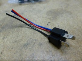
I have fallen in love with using relays for wiring up stuff in my cars. It's simple really, once you use one relay ... you'll wanna use more and more of them. I'm going to be using 3 - 30Amp Changeover Relay with 5 Wire socket. There are 5 leds on these relays - 87, 87a, 85, 86 and 30. 30 - Power Source, 85 - Trigger/Switch, 86 - Ground, 87a - Normally Closed, 87 - Normally Open When power is applied via Pin 30, but the trigger/switch is TURNED OFF - Pin 87a will have power going to it, and Pin 87 will have NO power going to it. When power is applied via Pin 30, and the trigger/switch is TURNED ON - Pin 87a will shut off power, and redirect it to Pin 87, which will NOW have POWER going to it. This is where the LEDs will be turned on by Ignition, but turn off when the Low Beams are engaged. We are going to run 3 Relays in this setup.
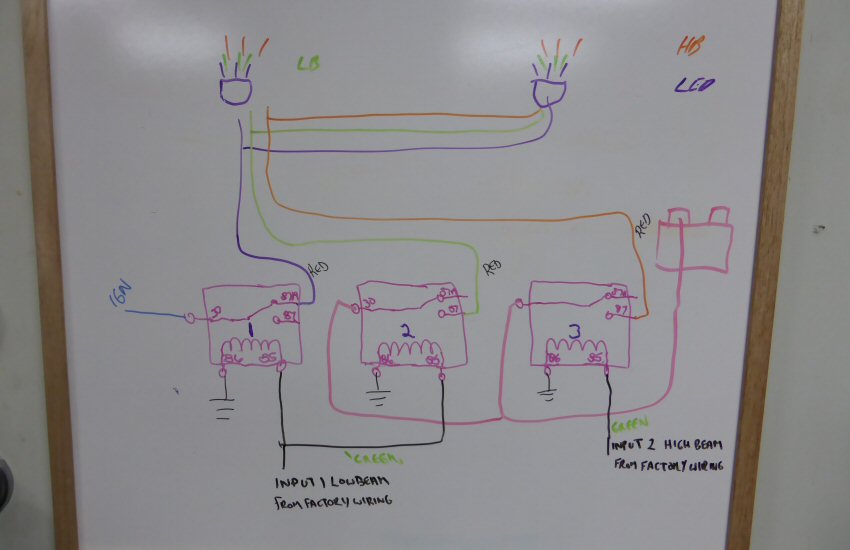
I have drawn a quick schematic on how I plan to wire all this up. Scroll to the BOTTOM of 'Page 2' or by clicking 'ON' the schematic picture below will open up a BIGGER version of the picture for ease of viewing.  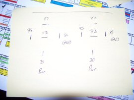 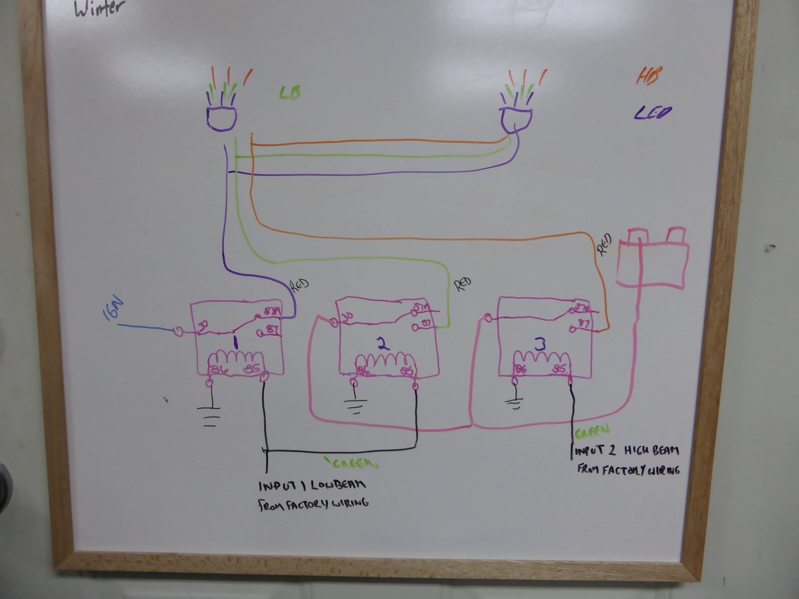
|
|
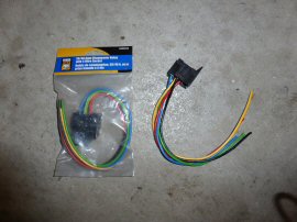
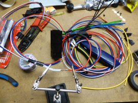
Picture #1 - I purchased 3x 30Amp 'Changeover' Relay with 5 Wire Sockets. It's important that you are using a Changeover relay for atleast Relay #1, as you need the 87a Pin. You could get away with a 'Make or Break Relay' (4 pin) for Relay #2 and #3. For ease of the project, I'm using 3 of the same. I like to keep things simple, and color coded and for this ... you will need to alter one of the 5 Relay Sockets. Picture #2 - There are 5 colored wires in the socket. Relay 1 will need a wire lead coming from 87a but not 87. I pulled out the YELLOW wire from Pin 87a and moved over the RED wire from Pin 87. I went one step further and removed the YELLOW wire from the Pin 87a from Relays 2 and 3 too. (Why have an exposed power wire, when you don't and won't need one). Moving the RED wire over on Relay 1 allows you to keep all the RED wires as POWER OUT for your LEDs/Headlights. Picture #3 - I've attached all the relay blocks together and begin tying up the wires together in groups.
|
|
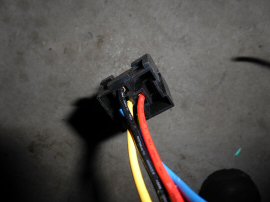
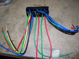
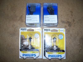
Picture #1 - I purchased some MALE & FEMALE H4/9003 Headlight Connectors for my external wiring circuit we will be using. Picture #2 - The Male H4 Connector will be used to plug our circuit into the FACTORY DRIVERS HEADLIGHT plug which is what we will use to trigger our relays. Picture #3 - I will be running 3 wires to each headlight from the relay install location.
|
|
Will run a set of 3 wires to the drivers headlight location, and then a second set of 3 wires will run along the front of the radiator cradle parallel to the factory wiring to the passenger side to the passenger headlight location. 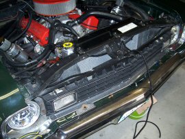 |
|
Picture #1 & #2 - All my wire connections and connections to the H4 headlight female connectors are solderied and shrink tubing used to seal them. Picture #3 - We will use the BLACK wire coming from the H4 headlight sockets and BLACK wire from the LEDs for GROUNDS. We simply just put a LOOP connector on the BLACK wire and bolt them straight to the radiator cradle. I also taped out the passenger side Headlight connector to avoid problems as it is not used. 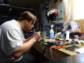 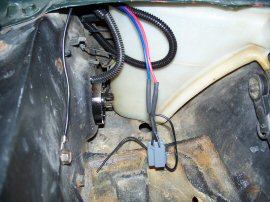 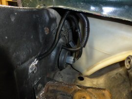
|
|
* The 'Headlight Female Plug' refers to the connector we are using to connect our custom headlight wiring harness to the factory headlight harness via the drivers side headlight plug. * The 'Male H4 Male Plug' refers to the connector on our NEW wiring harness we just built that will connect up our headlights. Relay #1 (30) BLUE - Power In : Connected/plugged into the IGN port on the fuse block INSIDE the car.
Relay #2 (30) BLUE - Power In : Connected to FUSED (15A) power wire connected to Positive on Car Battery
Relay #3 (30) BLUE - Power In : Connected to FUSED (15A) power wire connected to Positive on Car Battery
|
|
When HIGH beams/Relay #3 is engaged, power going to the trigger wire on Relay #1 turns off, thus switching the Relay #1 back into 'Normally Closed' mode turning back on the LEDs. So, the LEDs come out alongside the HIGH BEAMS. To keep the LEDs off with the HIGH Beams, you would need to install diodes in the trigger wires (GREEN) on Relay #1 & #2 to prevent the power from back feeding into Relays #1 & #2/other circuits. I left the LEDs on with the HIGH beams, as the idea with HIGH beams is to have the MOST amount of light possible. |
|
|
I installed a '4 Port Distribution Fuse Block' back when I first installed an Electric Fan. I did this, because I did NOT want to run multiple wires for power along the front of the car for my accessories. I installed a 4 port distribution port next to the radiator which will supply the power from the battery. This way I don't have to run multiple wires from the battery for all the accessories I've been wiring up. I am using a 10 gauge (10AWG) RED wire to bring power to the distribution port. Pulling power from the battery to power up the headlights is suppose to result in a brighter light, thus why we are installing additional relays for the LOW & HIGH beam. 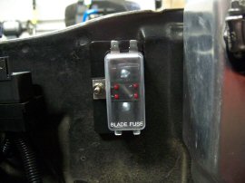 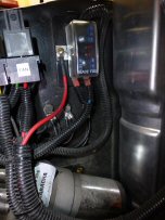 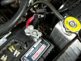
|
|
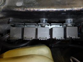
I used the same distribution point to draw the power I needed for Relay #2 & #3 to power the Headlights. Relay #1 pulls power from the fuse block on the IGNITION tab. I ran into an issue early after installation when washing the car at the local carwash. I found when I was washing the car, water was running in from the hood/fender lip, and there was the possbility of water traveling along the rad cradle and could possibly expose the relays/relay blocks to moisture causing a short. To try and correct this problem, I installed a couple of small spacers between the relays and Radiator Cradle wall. Also ensuring some space between the end of the fender/fender lip and relays below, will help avoid getting water on the relays.
|
|
Further efforts to making sure all the relays stay dry, I made up a quick cover to fit over top of with an old license plate. Cut, trimmed & bend it accordingly and it slides over to make sure water does NOT come into contact with the relays. 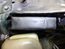 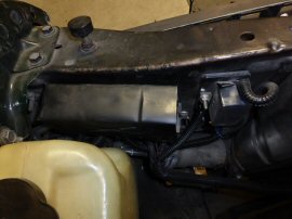 |
|
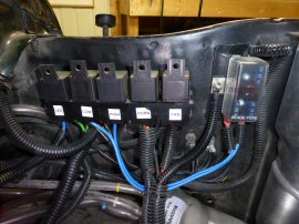
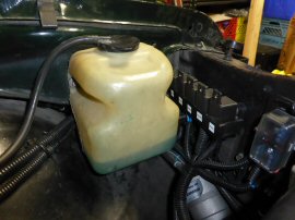
Although the install location on the Nova is nice and sort of hidden out of the way, I chose different location on my 74 Omega when wiring things up.
I made a small bracket which bolts to the fender and is located just behind the Washer Fluid bottle. This also allowed me to better hide the nest of wiring for a cleaner look and also avoid possible issues when washing the car. 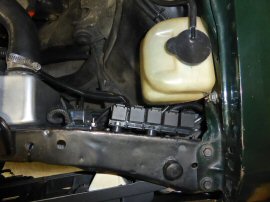 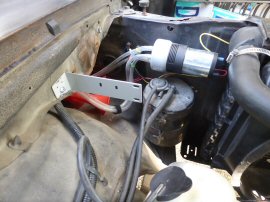 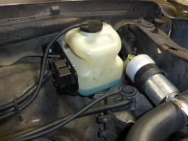
|
|
Here is an example of how it will ALL work after you are done.
This video will basically running through the various 'Light Cycles' - Ignition (LEDs On)
... and from High Beams, Low Beams, Markers Lights and Ignition Off. |
| Would like to thank 'Richard Reich' from the Facebook group 'Chevy Nova 73-74' for helping me make these instructions clearier and easier to follow and understand. Something I get sloppy or I jump around without being clear. |
|
|
|
 Main 'Project MEANGREEN' Page Main 'Project MEANGREEN' Page |
|---|
| Back to Photo Gallery - 2016 |
|---|
| Main Page |
|---|
| Email: davidmeier1 @ hotmail.com |